Drilling Top Weight / CG Position Blems with Powerhouse Blueprint
Date Posted:
December 3, 2011
Category:
Blueprint Tutorials
A very common topic in the bowling internet forums is the drilling of bowling
balls with unique undrilled static imbalances. This includes balls with
unusually high or low top weights, unusually long or short pin-to-CG distances,
and unusual center of gravity (CG) locations (such as those that are not located along the line from
the pin to the mass bias locator), all caused by natural manufacturing process
variation. These conditions are usually found on discounted "blems" or
"x-out" balls, often purchased online by bowlers looking for a good deal.
This article will explore the ways in which Powerhouse Blueprint can make the
drilling of such balls much easier on the pro shop operator.
Definitions
Before we begin, we'd like to establish a few definitions regarding an undrilled
ball's static imbalance so that there is no confusion going forward. First
off, most bowling ball manufacturers specify two parameters on the ball's box
relating to undrilled static imbalance:
- Pin-out distance: This is the distance of the CG mark to
the pin. This is often listed as a range of distances, such as 2"-3" or
4"-5".
- Top weight: This is the magnitude of the static
imbalance, usually listed in ounces.
For asymmetrical bowling balls, there is a third parameter that is necessary to
describe the undrilled static imbalance, and that is the location of the CG
relative to the pin / mass bias marker line. This is often not listed on
the ball's box, but must instead be measured on the ball itself.
For the purposes of this article, we will use the nomenclature of Powerhouse
Blueprint in describing undrilled static imbalance of asymmetrical balls, as shown in the below image:
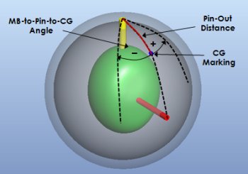
So then, the third parameter to describe the location of the CG is the angle
between two lines: 1) the line from the pin to the mass bias marker, and 2) the
line from the CG to the pin. The angle is expressed in degrees from -180 to
180, using the sign convention shown above. In this article, we'll refer to
this angle as the "MB-to-pin-to-CG angle", or, more simply, just the "CG angle."
Potential Challenges Encountered When Drilling Static Imbalance Blems
A lot can go wrong when drilling blems. Three main concerns of ball
drillers are listed below:
- Legality of as-drilled static weights: As we all know,
all drilled bowling balls must meet the top/bottom weight, side weight, and
finger/thumb weight requirements of the appropriate governing body (the USBC,
for example). With blems, the tendency is to be extremely conservative
with the layout used in order to be certain that the static weights will be
legal once the ball is drilled.
-
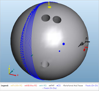
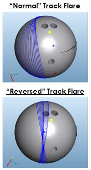 Reversing of track flare / flaring over a hole: When
drilling blems, it isn't unusual to use pin and mass bias placements that stray
from a ball driller's comfort zone, leading to concerns that the drilled ball
will flare over one of the ball's holes when thrown (which is an extremely
undesirable condition). An example of a ball with reversed track flare is
shown to the right in the bottom image. This ball will roll over the
middle finger hole during the last eight revolutions. Clearly, the
down-lane bouncing caused by this will have a very bad impact on the ball's
reaction.
Reversing of track flare / flaring over a hole: When
drilling blems, it isn't unusual to use pin and mass bias placements that stray
from a ball driller's comfort zone, leading to concerns that the drilled ball
will flare over one of the ball's holes when thrown (which is an extremely
undesirable condition). An example of a ball with reversed track flare is
shown to the right in the bottom image. This ball will roll over the
middle finger hole during the last eight revolutions. Clearly, the
down-lane bouncing caused by this will have a very bad impact on the ball's
reaction.
- Undesired on-lane ball reaction: In large part, the change in
ball reaction that a ball driller can impart through the choice of drill pattern
and balance hole position is caused by the resulting change in the flare
characteristics of the ball. This is due to the potential of track flare
to significantly change the amount of friction experienced between the
coverstock and lane when thrown, which is a function of the degree to which the
track flare rings overlap (generally speaking, tighter track flare ring spacing
results in lower friction and wider track flare ring spacing results in higher
friction...however, there is a point of diminishing return as flare ring
separation goes beyond a certain value). Since, as already stated above,
blems often require unconventional drillings that stray significantly from
well-understood drillings, it is entirely possible (and common) that a ball
driller could intend to drill a ball to flare very little, but accidently end up
with a ball that flares a lot (or vice-versa).
Now, with these potential problems in mind, let's take a look at how Powerhouse
Blueprint can help. We'll first outline a very high-level process and then
we'll look at a specific example.
Blueprint Ball Drilling Process Overview
What follows is a general process to follow for best results when drilling
bowling balls in Powerhouse Blueprint. This process applies to blems as well as
non-blems:
- Weigh and the undrilled bowling ball on an accurate (and calibrated) static
imbalance measurement device to determine its actual CG location and top weight.
While the manufacturer's CG mark and supplied top weight value are generally
reliable, it doesn't hurt to measure (and remark, if necessary) the ball yourself so that
you don't run into any unpleasant surprises after you've drilled the ball.
- Measure the pin-out distance and CG angle. This can be done quite easily using
standard pro shop measurement tools, such as the Pro Sect™.
-
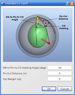 In Powerhouse Blueprint, load the appropriate bowling ball from the ball library
and then perform the core shifting operation to give the "virtual" ball the same
static imbalance as the actual ball to be drilled. This is done by
clicking Ball Operations => Shift Core from the main menu or by
clicking the corresponding toolbar button. For example, if the ball you
are drilling has 5 ounces of top weight, a 5 inch pin-out distance, and a -40
degree CG angle, you would enter these values
as shown to the right.
In Powerhouse Blueprint, load the appropriate bowling ball from the ball library
and then perform the core shifting operation to give the "virtual" ball the same
static imbalance as the actual ball to be drilled. This is done by
clicking Ball Operations => Shift Core from the main menu or by
clicking the corresponding toolbar button. For example, if the ball you
are drilling has 5 ounces of top weight, a 5 inch pin-out distance, and a -40
degree CG angle, you would enter these values
as shown to the right.
-
Virtually drill the ball using Blueprint however you like,
modifying the various drilling parameters (including balance hole position,
size, and pitch) to achieve the desired result. At this point of the process
"desired result" simply means that you drill the ball such that it is statically
legal and that the positive axis point (PAP) is placed in a location relative to
the min and max RG axes such that the ball's track flare will be close to what you want to see on-lane
(pin / mass bias placement relative to PAP, RG contours, etc. will be covered
in-depth in a future post, so we apologize if this description is a bit vague
right now).
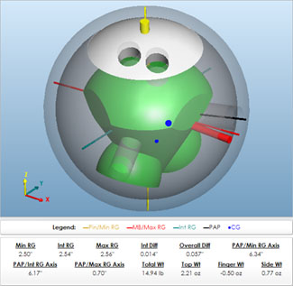 To continue our example, suppose we want to drill this ball to
flare very little. To do this, we'll attempt to position the PAP so that
it is far (approximately 6 inches) from the min RG axis and close (approximately
1 inch) to the max RG axis.
In this case, we've achieved this goal with a
drilling that places the pin 6 1/8 inches from the PAP with a 10 degree
MB-to-Pin-to-PAP Angle and a 30 degree Pin-to-PAP-to-VAL angle (commonly
referred to as a 10 x 6 1/8 x 30 drilling), with a large (1 inch diameter and 3
inch depth) balance hole on the PAP, pitched 2 inches horizontally away from
grip center. This is shown in the image above.
To continue our example, suppose we want to drill this ball to
flare very little. To do this, we'll attempt to position the PAP so that
it is far (approximately 6 inches) from the min RG axis and close (approximately
1 inch) to the max RG axis.
In this case, we've achieved this goal with a
drilling that places the pin 6 1/8 inches from the PAP with a 10 degree
MB-to-Pin-to-PAP Angle and a 30 degree Pin-to-PAP-to-VAL angle (commonly
referred to as a 10 x 6 1/8 x 30 drilling), with a large (1 inch diameter and 3
inch depth) balance hole on the PAP, pitched 2 inches horizontally away from
grip center. This is shown in the image above.
-
 Virtually throw the ball in Blueprint to see if it flares as desired. At this step,
it is critical that we make sure the ball is not flaring over any of the holes.
As shown to the right, our track flare in the above example looks to be exactly
as we've desired. If, alternatively, we had chosen a drilling that
resulted in an undesirable flare pattern, we could easily return to Step 4
above and make the necessary adjustments.
Virtually throw the ball in Blueprint to see if it flares as desired. At this step,
it is critical that we make sure the ball is not flaring over any of the holes.
As shown to the right, our track flare in the above example looks to be exactly
as we've desired. If, alternatively, we had chosen a drilling that
resulted in an undesirable flare pattern, we could easily return to Step 4
above and make the necessary adjustments.
Other Possible Drillings for the Example Ball
To illustrate the power of Blueprint's virtual ball drilling and on-lane motion simulation capabilities, we'll now continue the
above example and show a variety of drilling configurations that could be used
to achieve different on-lane reactions. To be clear, please keep in mind
that these are not drilling recommendations that we think people should be
using; rather, these are just random examples of ways in which this particular
ball could be drilled to illustrate the point that your options regarding the
drilling of blems aren't necessarily as limited as you might think they are at
first glance.
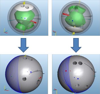
Here are two possible drilling options...
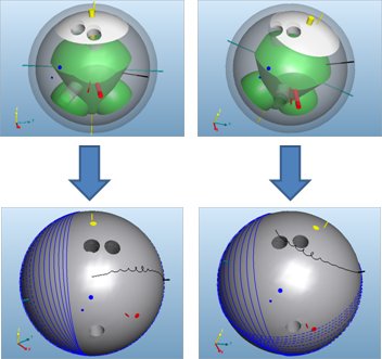
...and, here are two more, all four of which are legal with respect to static
imbalance.
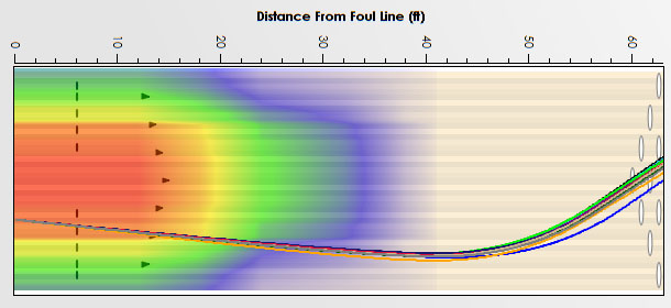
In terms of on-lane reaction, the drillings shown above result in a total hook
variation of about 5 boards, largely due to the changes in the track flare of
the ball:
Tips and Recommendations
We'll close this post by providing a couple of tips that you should keep in mind
when using Blueprint for simulated ball drilling (particularly in cases like
those shown here involving blems):
- Accurate bowler delivery input is critical. Make sure that you know a
bowler's PAP, ball speed, rev rate, axis tilt angle, and axis rotation angle
before attempting to use Blueprint for anything like what has been shown in this post.
Small errors in any of the input parameters can result in a drilled bowling ball
that isn't going to perform as predicted.
- Blueprint is not a replacement for actually checking the as-drilled static
weights on the scale. The static weights in Blueprint will track pretty
closely with the actual static weights measured on the scale, but there will be
slight differences.
- Because Blueprint can't perfectly predict static weights, try to leave yourself
an "out" when you have predicted static weights that are close to the legal
limits. What we mean by this is that you should always, when possible,
have a plan for what you can do to fix a ball that has already been drilled, but
checks slightly illegal on the scale. For example, if Blueprint predicts
0.90 ounces of finger weight, make sure that you have some room to increase the
finger hole depths in the event that the static weight scale shows the drilled
ball to have 1.10 ounces of finger weight, for example. You can, in many
cases, employ the same strategy with balance hole depths. Leaving yourself
an out post-drilling can save you a lot of trouble and we highly recommend it,
when possible.
- Don't "push your luck" too far. For example, try not to drill a ball that
comes within 1/64" of hitting one of the holes in the Blueprint simulation. Why?
Your bowler delivery parameters are not perfectly accurate, the mass properties
of the real ball aren't 100% accurate due to manufacturing process variation,
and the bowler will have natural variation in release consistency. For
these reasons, a ball that doesn't hit any holes in Blueprint may occasionally
(or frequently) hit a hole in real life if you haven't left yourself enough of a
"buffer" to allow for these variations. For an average bowler that has
never been Blueprinted by you before, we would recommend that you try to
maintain a 1 inch buffer between the closest track flare line and hole edge.
For elite bowlers (with consistent releases) and those that you have a lot of
experience with, you can relax this requirement slightly.
We hope this post has been informative, helpful, and useful to you in getting
the most out of Powerhouse Blueprint. In a future post, we'll share with
you some additional information about using Blueprint to squeeze that last
10-20% of performance out of a ball using some (as far as we know) previously
unused drilling methods.